Product family

Planetary Track Drives

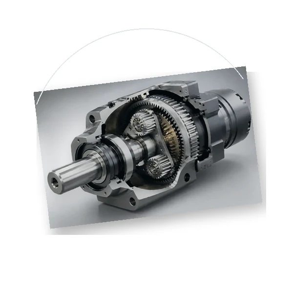
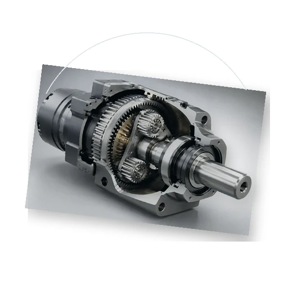
EP400-series track drives with rotating housing-flange support and hydraulic-motor interface options.

Category overview

Define the complete engineering context

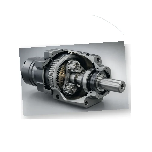
Track drives combine a planetary reduction stage with a rotating housing flange suited to tracked-machine interfaces. The model table links maximum torque, ratio range, input speed and optional braking data.

  • Controlled tooth and mating-part data
  • Installation datums and interface envelope
  • Duty cycle, environment and acceptance method
EP400 track drive dimension and parameter view
EP400 track-drive technical reference view from the product range.

RFQ product range

Planetary Track Drives products

Select a product family to review its drawing inputs, mating relationships, duty questions and inspection planning.

EP400 L1 planetary drive product view

EP400 L1 Planetary Track Drive

EP400 L1 planetary track drive combines a listed 1,000 N·m maximum torque, 5.25 ratio selection and 1,000 rpm maximum input speed with a machine-side rotating housing flange for track and sprocket mounting. These figures support a focused first review of motor, brake, mounting and duty requirements.

Review RFQ inputs

EP405 L2 planetary drive product view

EP405 L2 Planetary Track Drive

EP405 L2 planetary track drive combines a listed 10,000 N·m maximum torque, 20–53 ratio selection and 3,000 rpm maximum input speed with a machine-side rotating housing flange for track and sprocket mounting. These figures support a focused first review of motor, brake, mounting and duty requirements.

Review RFQ inputs

EP415 L3 planetary drive product view

EP415 L3 Planetary Track Drive

EP415 L3 planetary track drive combines a listed 85,000 N·m maximum torque, 100–156 ratio selection and 3,000 rpm maximum input speed with a machine-side rotating housing flange for track and sprocket mounting. These figures support a focused first review of motor, brake, mounting and duty requirements.

Review RFQ inputs

Application context

Where this product family is used

Crawler and tracked machinery

Final-drive layouts where the output housing rotates with the track sprocket.

Material-handling equipment

Compact tracked platforms requiring hydraulic drive and parking-brake integration.

Special mobile machines

Custom tracked equipment with shock, slope-holding and contamination requirements.

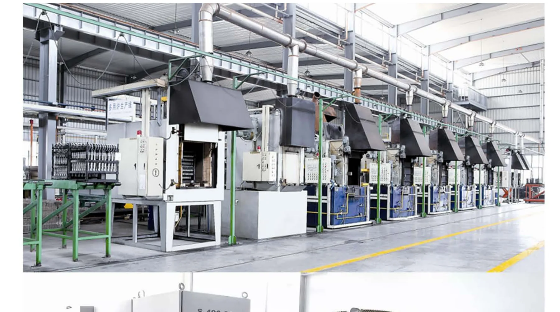
Manufacturing line shown in the product range
Planetary Track Drives engineering review

Engineering basis

Interfaces deserve the same discipline as the internal gearing. Define the input driver, adapter, shaft or spline, output shaft or flange, pilot diameters, fastener pattern, load application point, and the space available for installation and service. When the drive supports external radial or axial load, show the force direction and distance from the bearing reference. When the drive couples to a wheel, track sprocket, slew ring, rack pinion, pulley, or drum, include the mating geometry. Those details often decide whether a model that looks adequate for planetary track drives is actually suitable in the machine. Thermal and lubrication questions should be resolved before release rather than after a prototype runs hot. State ambient temperature, operating hours, input speed, duty cycle, mounting orientation, expected ventilation, and whether the gearbox is inside an enclosure. Confirm lubricant type, viscosity or manufacturer-approved grade, fill quantity, fill and drain access, and any oil-circulation or cooling requirement. The purpose is not to add paperwork; it is to ensure that the selected arrangement can maintain a stable oil film and acceptable temperature while delivering a defensible family-level shortlist. Acceptance criteria should be tied to function. For a precision axis, backlash, torsional stiffness, runout, pitch or tooth accuracy may matter. For mobile equipment, brake release, holding behavior, sealing, valve integration, and output-bearing loads may dominate. For process machinery, temperature, leakage, vibration, shaft loading, and service access may be more important. Define which characteristics are controlled on the drawing, which need inspection records, and which are verified by a functional test. This evidence-based approach reduces ambiguity around planetary track drives and gives both buyer and supplier the same release target.
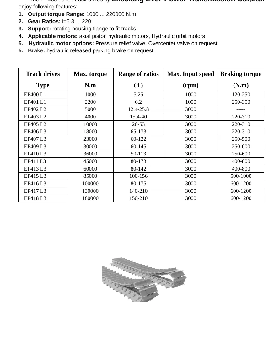
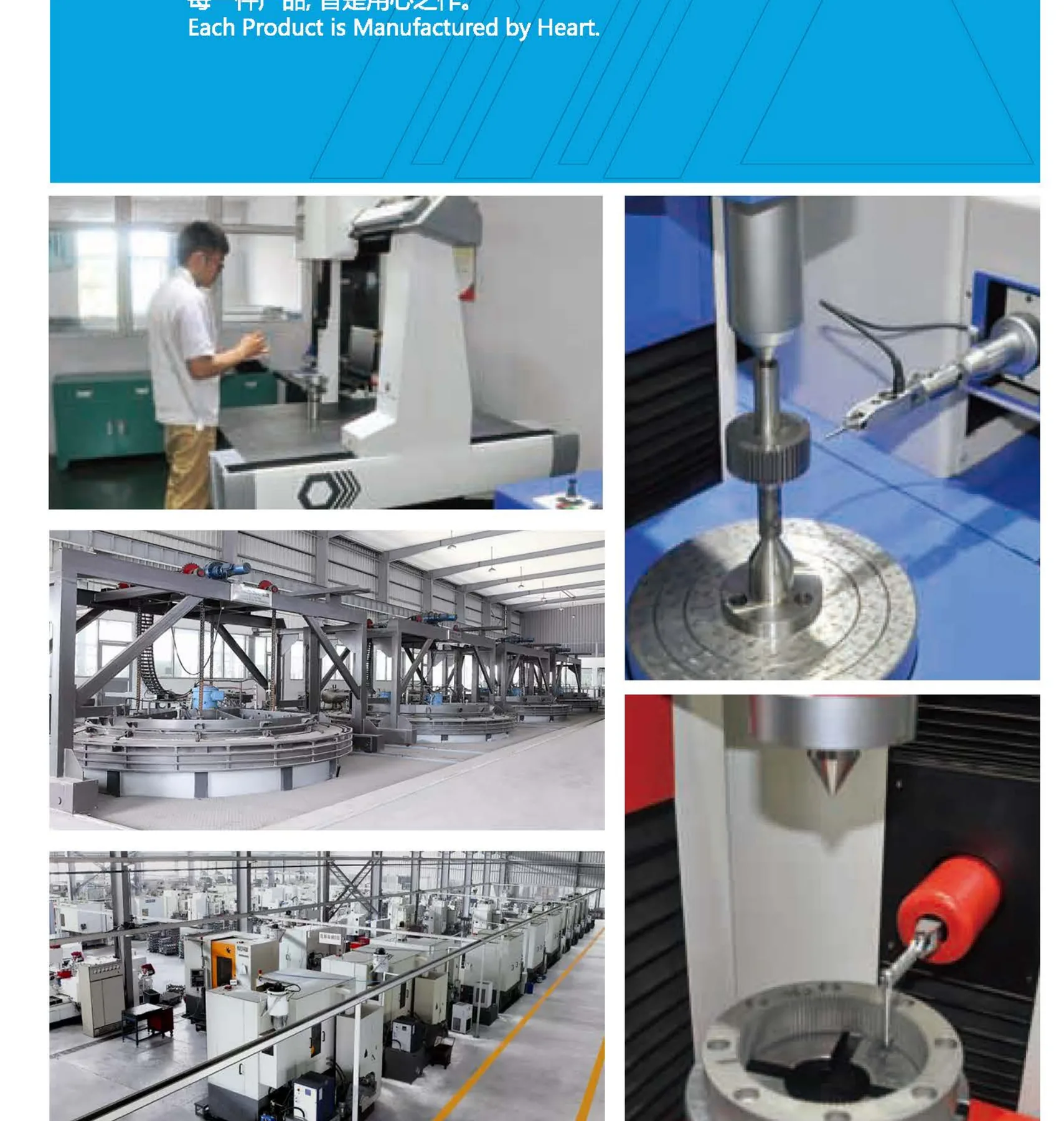
Inspection and test equipment shown in the product range
Planetary Track Drives engineering review

Duty and interfaces

When information is incomplete, mark the gap instead of replacing it with an invented value. A useful RFQ can still proceed with an application sketch, motor data, target motion, estimated duty, and the known interfaces, provided the missing confirmation is visible. The supplier can then return a data-request list or a provisional configuration. For Planetary Track Drives, the key is traceability: the final model, ratio, mounting, options, and acceptance method should all map back to the operating conditions that justified them. A final cross-check should ask what happens if one assumption changes. Consider a higher start frequency, a larger wheel or pinion radius, a warmer ambient condition, a different mounting orientation, or a new external load. If any of those changes can invalidate the selection, record the dependency in the quotation notes. That practice is particularly valuable for planetary track drives, because it prevents a technically correct selection from being copied into a second machine with a materially different duty. The released configuration should therefore be treated as application-specific, even when it belongs to a standard product family. Planetary Track Drives should be treated as an engineering decision about planetary track drives, not as a lookup exercise. The first objective is an application-specific model choice. Begin with the machine function and document the operating point in units that can be checked independently: torque at the driven member, rotational or linear speed, the timing of acceleration and deceleration, and the duration of normal and peak conditions. For planetary track drives, that sequence matters because the same nominal power can produce very different gearbox loads when ratio, inertia, start frequency, or external forces change. The working record should explicitly cover maximum torque, ratio range, input speed, brake, mounting.

Manufacturing line shown in the product range
Planetary Track Drives engineering review

Verification and release

A strong review separates source-backed product data from application assumptions. Published model values can define a feasible envelope, but the machine-side calculation remains the buyer or system designer input until it is confirmed. In the context of planetary track drives, record which values came from a controlled drawing or product source, which were calculated from machine geometry, and which remain provisional. This prevents unclear acceptance after order. It also makes later changes easier to manage because an engineer can see whether a revised motor, wheel radius, duty cycle, or mounting arrangement changes the gearbox requirement or only the surrounding interface. The selection should be checked at more than one operating condition. A normal production point establishes continuous demand; an acceleration or start point establishes short-duration torque; a jam, emergency, wind, slope, or braking event may establish a separate peak. Each condition should carry a duration and expected frequency. That distinction is especially important when reviewing planetary track drives, because mechanical capacity, bearing life, brake capacity, and thermal capacity do not respond to load in the same way. A concise duty table is more useful than a single oversized safety factor, and it gives the supplier a reproducible basis for confirming traceable acceptance evidence. Interfaces deserve the same discipline as the internal gearing. Define the input driver, adapter, shaft or spline, output shaft or flange, pilot diameters, fastener pattern, load application point, and the space available for installation and service. When the drive supports external radial or axial load, show the force direction and distance from the bearing reference. When the drive couples to a wheel, track sprocket, slew ring, rack pinion, pulley, or drum, include the mating geometry. Those details often decide whether a model that looks adequate for planetary track drives is actually suitable in the machine.

Selection variables to include in the RFQ

Data group Information to provide
Maximum torque Use the model table as a ceiling and verify service-factor-adjusted required torque.
Ratio range Match vehicle speed, motor speed and tractive effort.
Input speed Check the hydraulic motor operating range against the catalogue limit.
Brake Define parking and holding requirements, release pressure and control logic.
Mounting Confirm both flange patterns, sprocket offset and available axial length.

Category FAQ

Can a track drive be selected by machine weight only?

No. Tractive effort, gradeability, sprocket radius, speed, duty and braking conditions are also needed.

Are hydraulic valves included automatically?

The catalogue lists relief and overcenter options on request; the quotation must state the required hydraulic circuit scope.

Engineering enquiry

Send the category-specific RFQ inputs

Attach the drawing or assembly sketch and identify the controlled geometry, interfaces, operating duty and required inspection records.

Email the engineering brief

quote form