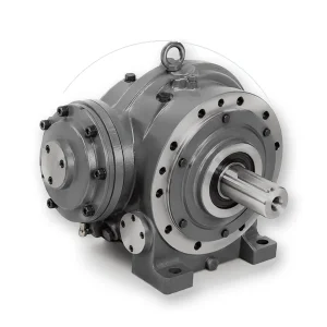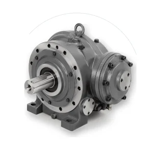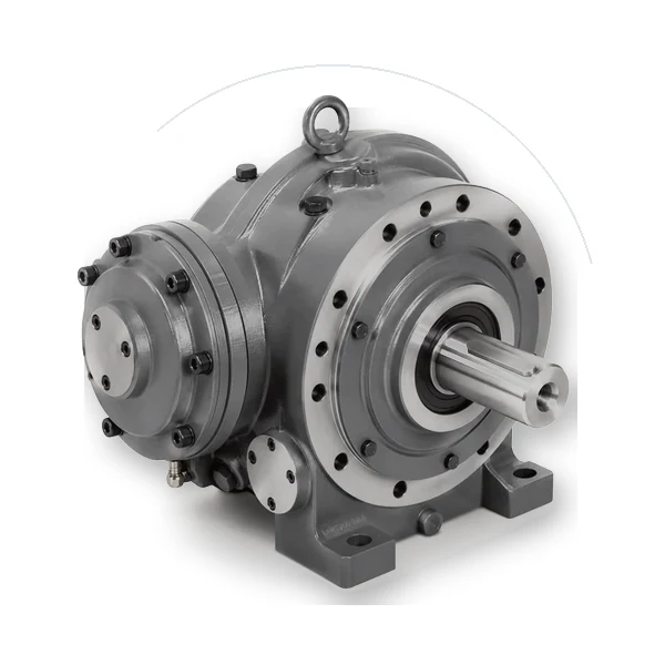
EP615 L3 Planetary Wheel Drive
EP615 L3 planetary wheel drive combines a listed 60,000 N·m maximum torque, 108 ratio selection and 3,000 rpm maximum input speed with a machine-side rotating flange for wheel or drum mounting. These figures support a focused first review of motor, brake, mounting and duty requirements.
Dimension & interface review
Confirm the exact configuration before releasing mating parts
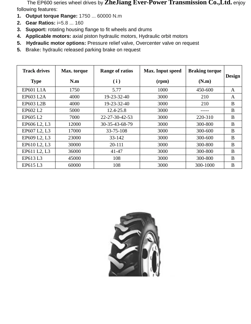
EP615 L3 is a listed EP-series wheel drive. Its sample table publishes a maximum torque value of 60,000 N·m, a ratio selection of 108 and a maximum input speed of 3,000 rpm for the listed configuration.
EP615 L3 Planetary Wheel Drive represents one specific size/stage option within the planetary wheel drive family. Compare its listed torque, ratio and input-speed row with adjacent sizes before freezing the machine interface.
Use the dimensional reference to check locating pilots, bolt circles, shaft or flange geometry, overall envelope and service access. The purchase description should identify the exact model or frame, ratio, stage count and interface option rather than relying on the family name alone.
Planetary wheel drive
Product overview and selection position
EP615 L3 planetary wheel drive combines a listed 60,000 N·m maximum torque, 108 ratio selection and 3,000 rpm maximum input speed with a machine-side rotating flange for wheel or drum mounting. These figures support a focused first review of motor, brake, mounting and duty requirements.
The model is organized around a rotating flange for wheel or drum mounting. Use the listed figures to shortlist the drive, then verify service factor, braking, hydraulic controls, output loads and mounting dimensions for the machine.
Wheel-drive selection should start from force at the tire or drum, effective radius, speed and duty. Verify bearing loads and brake/holding requirements independently from gearbox torque.
Start the RFQ with the driven-machine requirement. State the normal operating point, the acceleration or start condition, any emergency or jam peak, the direction of rotation, starts or reversals per hour and the expected operating schedule. Keeping those load cases separate makes it possible to compare mechanical capacity, bearing duty, brake requirements and thermal behavior without hiding the real duty behind one oversized factor.
Listed specifications and what they mean
| Parameter | Listed value | Engineering check |
|---|---|---|
| Model | EP615 L3 | Confirm the complete construction and design suffix. |
| Maximum torque | 60,000 N·m | Check required and shock torque with the application duty. |
| Ratio | 108 | Confirm motor speed and required output speed. |
| Maximum input speed | 3,000 rpm | Check continuous duty and motor operating range. |
| Output support | rotating flange for wheel or drum mounting | Verify flange, shaft or pinion drawing. |
| Input options | Hydraulic motor; electric options by family | Define adapter, valves and brake scope. |
The values above are screening inputs for the exact product family or model. A final selection should reconcile the listed row with motor speed, calculated output torque, service or dynamic factor, required working life, mounting orientation and the surrounding machine structure. If a value needed for the decision is not listed for the chosen configuration, keep it as an explicit confirmation item in the quotation.
Architecture, stages and mechanical interfaces
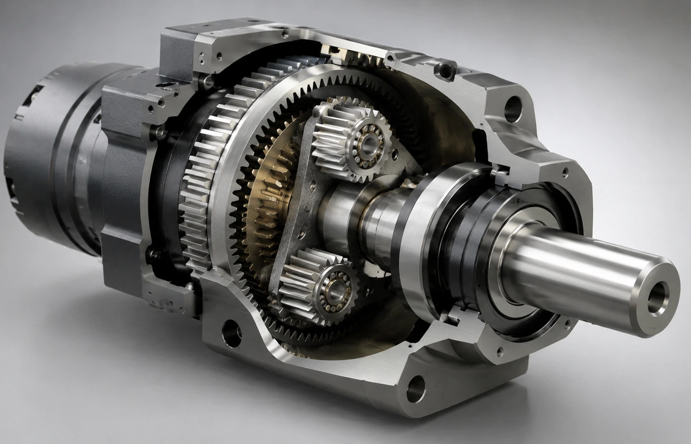
The wheel-drive package combines planetary reduction with the machine-side support geometry. Confirm rotating flange for wheel or drum mounting, input motor pilot and shaft, brake release requirements, valve block scope, rotation direction, lubrication access and the exact dimensional drawing before release.
The internal epicyclic arrangement distributes torque through the sun, planet gears, carrier and ring gear, while the housing and bearings transfer those forces into the machine. Torque capacity and interface capacity are related but not interchangeable. A gearbox can meet nominal torque and still be unsuitable if an overhung pulley, sprocket, wheel or pinion creates excessive bearing load.
Define the motor pilot, motor shaft, coupling or input spline, output connection, locating diameter, fasteners and load application point on the same interface drawing. Confirm rotation direction and any brake-release, valve or sensor connections before the surrounding bracket, wheel hub, sprocket or machine plate is machined.
Application duty: calculate the load at the driven member
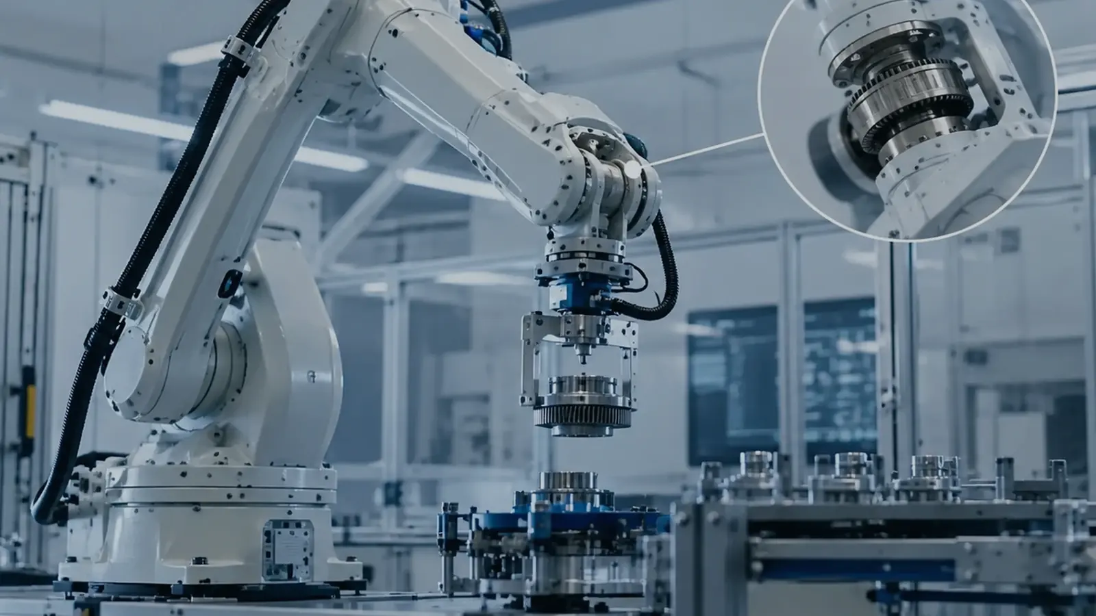
EP615 L3 can be considered for industrial vehicles, AGVs, mobile platforms and drum drives. Machine mass alone is not a sufficient selection input; calculate torque from tractive or slewing force, radius, gradient, acceleration, duty cycle and shock events.
This family is used in mobile platforms, industrial vehicles and drum-drive systems where wheel radius, tractive force, speed, braking and external loads govern the drive. Translate the machine requirement into torque at the gearbox output and keep the calculation traceable. For a wheel, track sprocket, pinion, drum or pulley, include the effective radius. For a servo axis, include inertia and acceleration. For a slewing structure, include acceleration and external moments or holding conditions that occur while the structure is stationary.
Do not combine every event into one continuous load. A normal production point establishes sustained demand; acceleration and reversal establish dynamic peaks; holding, braking, wind, slope or jam events may form separate cases. Their duration and frequency affect thermal and life calculations differently, so they should remain distinct in the RFQ.
Motor, ratio and speed matching
Calculate the target reduction from the working motor speed and required output speed, then choose an actual listed ratio for the selected frame or stage arrangement. Recalculate output speed with that real ratio rather than carrying an ideal ratio into the released machine. Also check the motor torque-speed curve at the expected operating points; a ratio can satisfy output speed while moving the motor into an undesirable torque or speed region.
Input speed matters mechanically and thermally. State whether the machine runs continuously, indexes intermittently or spends long periods at low speed under load. For electric drives, include the exact motor model and control regime. For hydraulic inputs, include motor type, displacement range, operating pressure and flow where known. If a brake or holding function is required, define whether it is for parking, emergency stopping or controlled holding and keep that requirement separate from the transmission torque calculation.
External loads, mounting and bearing checks
- Hydraulic or electric input data
- Output flange/spline/pinion drawing
- External radial, axial and overturning loads
- Parking or holding brake requirement
- Relief or overcenter valve scope
- Contamination, temperature and sealing conditions
For every radial or axial load, show magnitude, direction and the distance from the relevant shaft or flange reference. Belt tension, chain pull, gear mesh force, wheel reaction and slew-pinion force can all create bearing loads that are not visible in the gearbox torque number. When the load point moves outward, the resulting bearing moment can increase even if transmitted torque is unchanged.
Mounting orientation also affects lubrication level, plug position, service access and sometimes the permitted input arrangement. Confirm whether the gearbox is horizontal, vertical or inclined in the machine, and leave practical access to fill, drain, inspection or brake connections. A dimensionally correct installation that cannot be lubricated or serviced is not release-ready.
Manufacturing and dimensional-control checkpoints
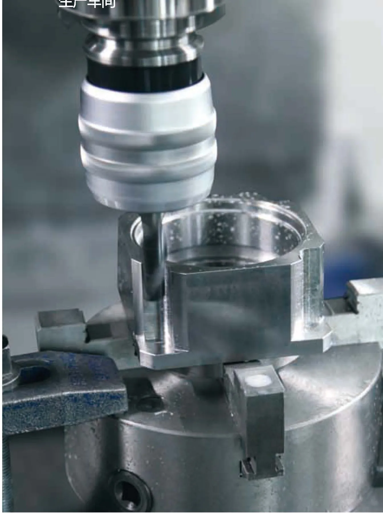
The product geometry that locates the gearbox in the machine should be treated as controlled interface data. Identify pilots, flange faces, shaft fits, bolt circles, key or spline features and any runout or concentricity requirement that affects alignment. If a custom adapter, pulley, pinion or bracket is part of the project, place its revision on the RFQ so both sides are checking the same geometry.
Do not use broad quality language as a substitute for measurable acceptance points. Decide which dimensions or functions matter to assembly and machine performance, then request the corresponding inspection or functional record when it is commercially required.
Inspection, installation and commissioning
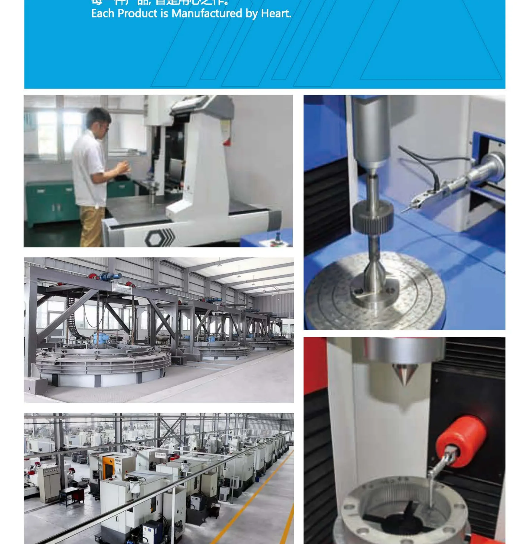
Inspect the mounting flange, output geometry, input interface, brake release and free rotation against the approved drawing. For mobile drives, functional acceptance should also define leakage, brake holding or hydraulic tests when they are included in the scope.
Before assembly, verify the model code, ratio, mounting orientation and interface drawing against the purchase order. Clean locating surfaces, avoid forcing shafts or pilots together, and align couplings, wheels, sprockets or pinions so the gearbox is not used to correct machine misalignment. Tightening, lubrication and brake or hydraulic connections should follow the released product instructions for the exact configuration.
At commissioning, record rotation direction, no-load behavior, leakage condition and the first operating temperature trend. Where applicable, verify brake release/holding, valve operation, backlash or lost motion, runout or other project-specific acceptance points. Retain that baseline with the machine record so later troubleshooting can distinguish an installation issue from a change in operating duty.
Maintenance and failure-risk review
Maintenance planning should be linked to the installed orientation and duty. Keep lubricant type and fill quantity with the machine documentation, make inspection points accessible, and record any periodic brake, seal or connection checks required by the final configuration. A change in lubricant, mounting angle, external load or ventilation should trigger an engineering review rather than being treated as a routine service substitution.
Common selection risks include using family maximum torque as a continuous rating, omitting the distance of an overhung load, selecting an ideal ratio that is not an offered ratio, ignoring the thermal effect of continuous high input speed, or releasing a motor adapter before the exact motor shaft and pilot are known. A short pre-release checklist is usually cheaper than correcting any of those mismatches after machining or assembly.
Frequently asked engineering questions
Can this model be selected from machine weight?
No. Required output torque also depends on radius, speed, acceleration, gradient, friction, duty and shock load.
Is the brake included?
The product catalogue lists brake options for relevant models. The quotation must state brake torque, release method and control scope.
Are hydraulic valves included?
Relief and overcenter options are available for some families. Specify the circuit and valve functions required.
What drawing should accompany the RFQ?
Provide the machine-side flange, sprocket/wheel/slew-ring interface, motor interface and available axial envelope.
Related selection path
Compare the planetary wheel drive family, then use the epicyclic gearing selection guide to organize duty, motor and interface inputs before quotation.
For replacement work, also provide the existing unit identification, installation photographs, the reason for replacement and the dimensions that cannot change. For a new machine, a marked-up concept drawing is sufficient to begin as long as unknown values are clearly identified.
Engineering RFQ
Request a configuration review for EP615 L3 Planetary Wheel Drive
Reference GEP-EP615-L3 and include torque or force, motor speed, target output speed or ratio, mounting orientation, external loads and the motor/output interface drawing.