Engineering guide
Internal Ring Gear RFQ: Geometry, Datum and Inspection Questions
Internal teeth, surrounding shoulders and mounting features make ring-gear sourcing a system-level task.
Start with the mating mesh
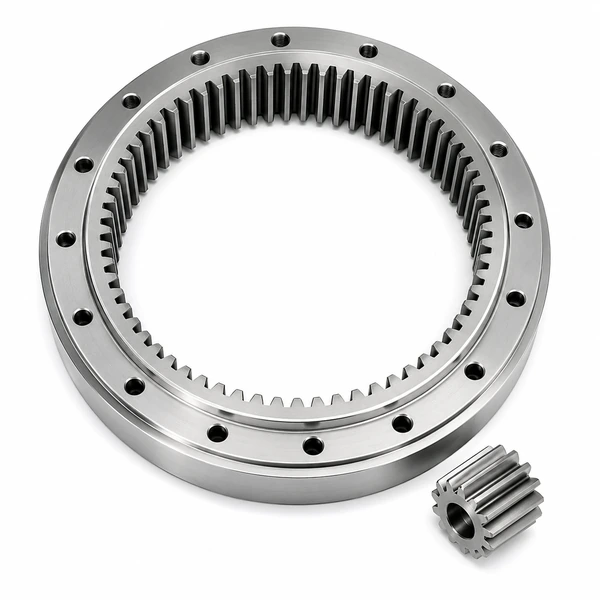
Provide the complete tooth definition for the ring and mating planet gears. Tooth count alone is not enough. The RFQ should identify the tooth system, profile data, face width, tooth-thickness or backlash basis and assembly condition.
If the ring is a replacement component, include the approved drawing and explain whether the mating gears will be reused, replaced or inspected.
- Ring tooth definition
- Mating planet data
- Approved assembly condition
Choose functional datums
Identify the feature that locates the gear in the machine: outside diameter, pilot, mounting face, flange, bolt pattern or another controlled surface. Then define the relationship between that datum and the internal teeth. A nominally correct tooth form can still produce poor mesh alignment if the mounting relationship is unclear.
- Primary installation datum
- Tooth-to-datum runout relationship
- Mounting-face and pilot controls
Review manufacturing access
Internal gear cutting and finishing require tool and measurement access. Nearby shoulders, small bore diameter, long face width, thin wall sections and heat-treatment distortion risk can change the route. Share the full blank geometry so manufacturability is not assessed from the teeth alone.
- Cutter access
- Heat-treatment allowance
- Measurement access
Agree the inspection basis
| Characteristic | RFQ clarification |
|---|---|
| Tooth thickness or space width | Measurement method, condition and relationship to backlash. |
| Pitch and runout | Specified datum and required report form. |
| Profile and lead | Required traces, sampling and flank definition. |
| Mounting features | Concentricity, perpendicularity and face relationship. |
| Functional mesh | Mating master, rolling condition or assembly check when required. |
Avoid unsupported substitutions
A supplier may propose material, heat treatment or geometry adjustments, but a proposal is not an approved substitution. Record the reason, technical impact and drawing revision. For reverse-engineered work, clearly separate measured observations from values inferred or selected by engineering.
- Document the reason for change
- Assess fit and duty impact
- Approve the revised drawing
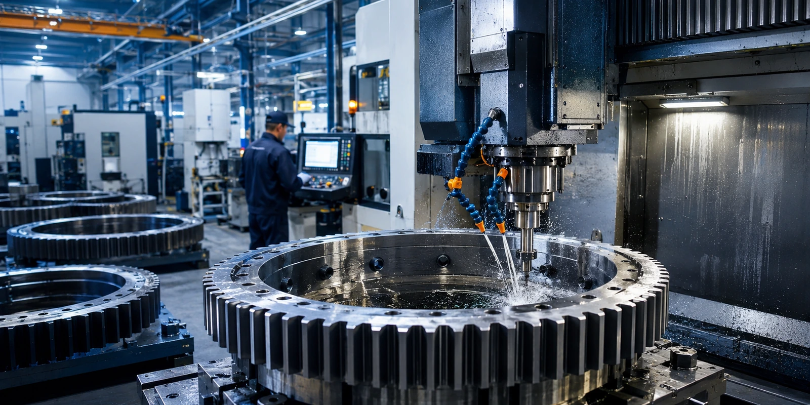
Review manufacturing access around the internal teeth
Blind sections, nearby flanges, small reliefs and limited tool overrun can change the feasible cutting and finishing route. Show the complete surrounding geometry rather than cropping the drawing to the tooth data alone.
Confirm whether the supplier may add reliefs, increase tool-clearance areas or adjust non-functional surfaces. If these features cannot change, the drawing should mark them as controlled constraints before the process route is proposed.
- Show tool approach limits
- Mark controlled shoulders and reliefs
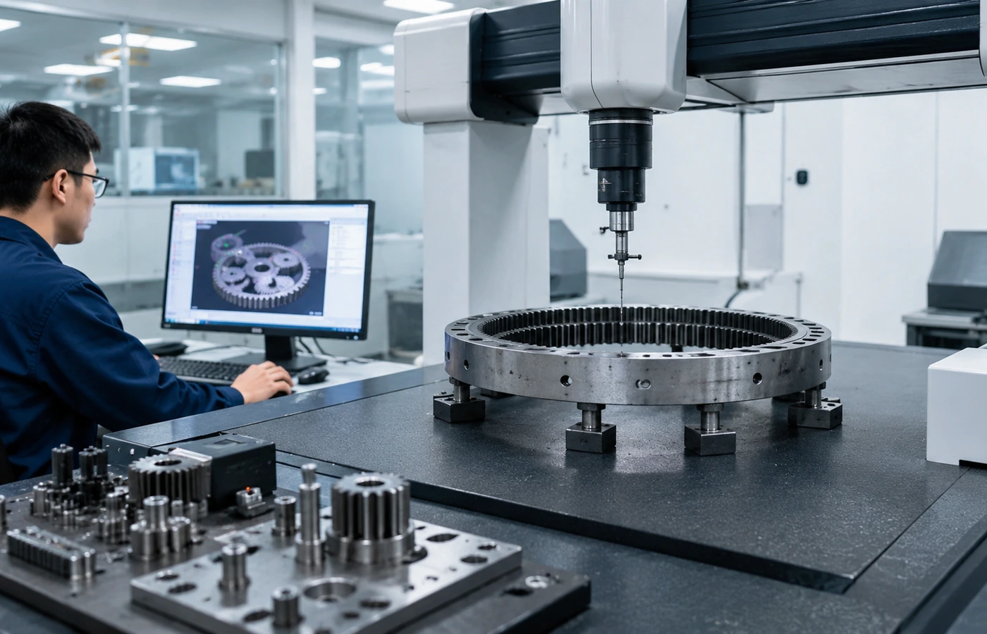
Correlate gear inspection with installation datums
Agree how tooth thickness, profile, lead, pitch and runout are referenced to the bore, pilot, outside diameter or flange face that locates the ring in the machine.
Include the expected inspection orientation, any fixture or master information and the report format needed by the receiving team. This avoids a technically valid tooth report that cannot be correlated with the assembled condition.
- Name the locating datum
- Define report and fixture requirements
Engineering enquiry
Use the guide to prepare your RFQ
Send the relevant drawing, duty and interface data. The technical review will identify confirmation points before any product claim or geometry is approved.
- Drawing or assembly sketch
- Duty and interface summary
- Quantity and inspection needs