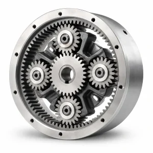
Description
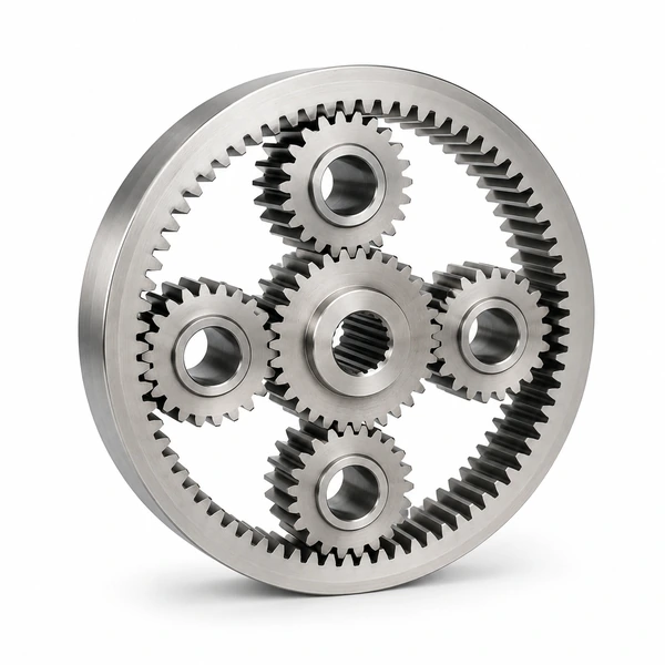
RFQ product family
Sun and Planet Gears
Sun and planet gears are external members whose geometry, bore interfaces and support conditions must align with the internal ring and carrier.
RFQ identifier: GEP-SPG-001
Start with
- Controlled drawing or assembly sketch
- Complete mating-tooth definition
- Input, output and restrained-member relationship
- Duty cycle and speed range
- Interface and inspection requirements
Product overview
This family covers loose external gears for a new or existing epicyclic arrangement. The sun may include a bore, spline, integral shaft or coupling interface. Planet gears require a defined bore, bushing or bearing arrangement and axial retention. The quotation should identify whether planet gears are interchangeable, matched by group or assembled to controlled carrier positions.
This page defines a quotation scope rather than a stocked configuration. Tooth numbers, size, material, heat treatment, backlash, accuracy class and acceptance limits remain confirmation points until they are supported by the buyer’s controlled data and an approved technical proposal.
Structure and mating components
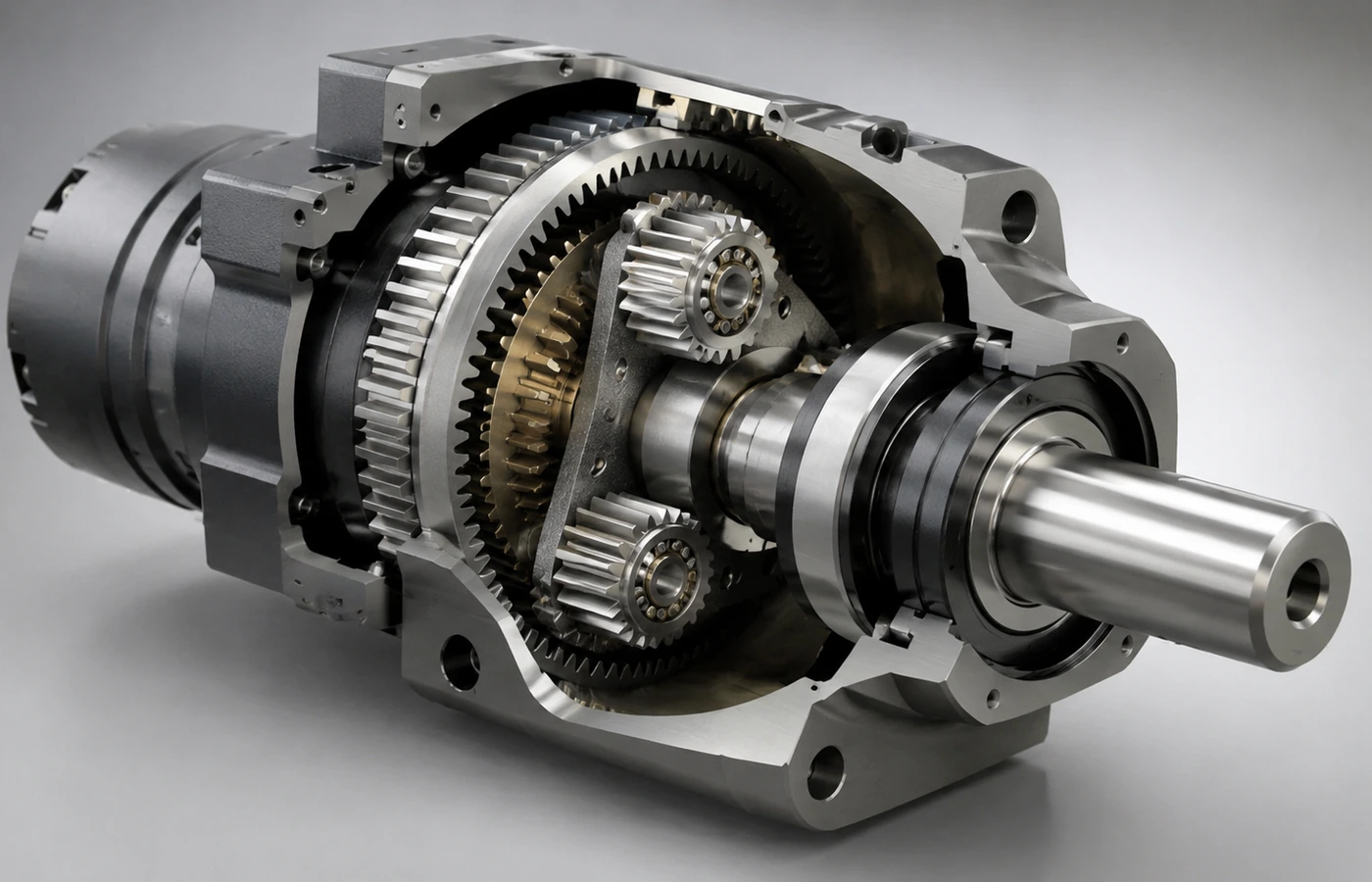
An epicyclic component works inside a system of related datums and load paths. The sun gear, planets, carrier, ring gear, bearings, shafts and housing influence mesh alignment. Even when the RFQ covers one loose gear, the mating geometry and support arrangement are needed to assess fit and manufacturability.
For the sun, provide the motor or input-shaft connection and axial location. For planets, define pin diameter, bearing or bushing, end faces, clearances and carrier spacing. Include the mating ring gear data and the intended number of planets.
Technical definition required for quotation
| Data group | Information to confirm |
|---|---|
| Tooth system | Module or diametral pitch, pressure angle, tooth count, helix data where applicable, profile and lead requirements. |
| Geometry | Face width, tip and root controls, bore or spline, shoulders, pilots, bolt pattern and datum relationships. |
| Mesh | Mating part data, backlash or tooth-thickness basis, center-distance relationship and assembly condition. |
| Duty | Continuous, peak, shock and reversing load description with input and output speed ranges. |
| Material route | Controlled material grade, heat treatment, hardness requirement, finish allowance and surface protection. |
| Verification | Critical characteristics, inspection method, report format, sample plan and traceability expectation. |
Application and operating context
External members can be used in automation reducers, industrial transmissions, test rigs and replacement gearboxes. Reversing duty, high start frequency or shock loading should be described separately from normal operation.
State the machine function and installation environment rather than relying on a broad industry label. Temperature, contamination, corrosion, lubrication, orientation, external shaft loads and service access can affect the component and the surrounding assembly.
- Describe all operating modes
- Separate transmitted load from external shaft load
- Identify environmental and maintenance constraints
Selection and customization guidance
Can the geometry be proposed from a target ratio?
A concept review can begin with ratio, envelope and motion relationship, but released geometry also needs duty, interfaces, material route, manufacturability and acceptance criteria.
Can an existing part be reproduced?
A sample is useful context. A controlled drawing or agreed reverse-engineering scope is still needed to establish critical dimensions, material, heat treatment and inspection responsibility.
How should backlash be specified?
State the functional need, measurement condition and mating component basis. Backlash cannot be treated as a single isolated gear value without reference to tooth thickness, center distance and assembly conditions.
What quantity should be provided?
State prototype, validation and expected production quantities separately. This helps align tooling, process validation and inspection planning without creating a delivery promise.
Manufacturing and quality planning
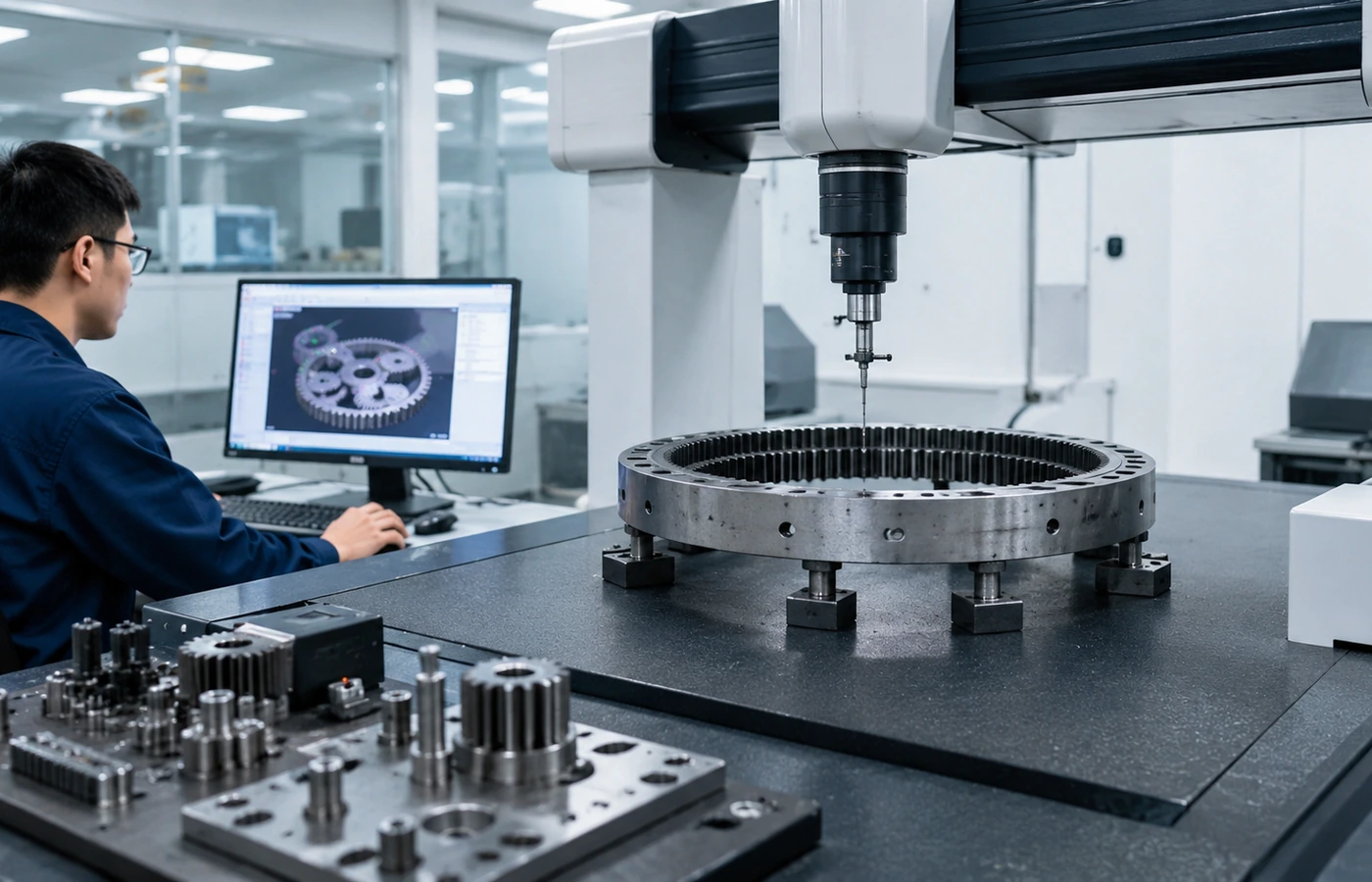
The manufacturing route may include blank preparation, turning, gear cutting, deburring, heat treatment, hard finishing, cleaning and protective treatment. The exact sequence depends on geometry and controlled requirements; it should not be inferred from a generic product photo.
Inspection should connect tooth geometry to bore or spline datums and, for planet gears, to the bearing surfaces. Confirm whether gears are released individually or as a matched group.
Before production, confirm the revision hierarchy, approval status, deviation process and records required at release.
RFQ questions and answers
Use these answers as a preparation guide. Final values remain subject to the controlled drawing and engineering review.
Is the sun integral with a shaft or supplied as a loose gear?
Clarify the quotation boundary and provide the shaft, bore, spline, keyway, shoulder and retention interfaces that control manufacture and assembly.
How are planet gears supported and retained?
Describe the planet bore, pin, bearing or bushing, thrust control, lubrication path and axial retention arrangement.
How many planets are used and how are they spaced?
State planet quantity, angular spacing and whether timing, selective assembly or matched tooth-thickness allocation is required.
What ring-gear data controls the internal mesh?
Provide the approved ring tooth geometry, datum relationship and assembled center-distance or backlash basis.
Are gears interchangeable or matched?
Define whether each gear must be individually interchangeable or released as a numbered matched set with assembly-level verification.
Which datum relationships require recorded inspection?
List the bore or spline, faces, journals and tooth features that require runout, concentricity or axial relationship records.
Engineering enquiry
Request a review for Sun and Planet Gears
Attach the drawing or sketch and describe the complete machine relationship. Unsupported values will remain open confirmation points rather than being converted into catalogue claims.
- Drawing or assembly sketch
- Duty and interface summary
- Quantity and inspection needs